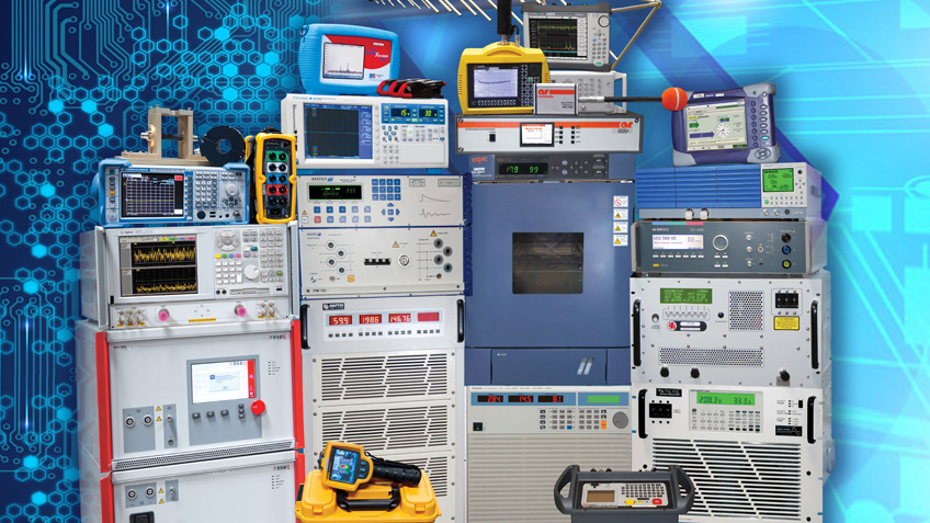

Automotive
Electromagnetic compatibility (EMC) is a characteristic of electrical and electronic equipment that permits it to operate as intended in the presence of other electrical and electronic equipment, and not to adversely interfere with that other equipment. All such equipment emits electrical energy, and some of that emitted energy may interact and interfere with other equipment. Equally, equipment may be susceptible to receiving energy emitted from other sources. Electrical equipment (including telecommunications equipment) intended to be fitted to a motor vehicle are considered to be 'Electronic Sub Assemblies (ESA)' and are required to meet Automotive EMC requirements. These requirements are set out in Directive 2004/104/EC, a specific Directive which forms part of European legislation for automotive type approval. The annexes of this Directive contain all the technical requirements necessary to demonstrate conformance which allows the ESA to be placed on the market.
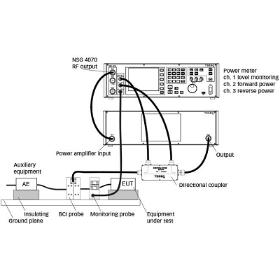
Bulk Current Injection (BCI)
Applicable Test Standards International Electrotechnical Committee (IEC) IEC/EN 61000-4-6: Electromagnetic Compatibility (EMC): Testing and Measurement Techniques – Immunity to Conducted Disturbances, Induced by Radio-Frequency Fields International Organization for Standardization (ISO) ISO 11452-4 Road Vehicles – Component Test Methods for Electrical Disturbances from Narrowband Radiated Electromagnetic Energy: Harness Excitation Methods Department of Defense Interface Standard MIL-STD 461: Requirements for the control of electromagnetic interference characteristics of subsystems and equipment Radio Technical Commission for Aeronautics (RTCA) RTCA DO-160 Environmental Conditions and Test Procedures for Airborne Equipment The conducted immunity test method Bulk Current Injection (BCI) has widely gained acceptance as an alternative or supplementary immunity test method to radiated immunity testing. It has been standardized by several organizations for a variety of applications from integrated circuits and subassemblies for automotive applications and aerospace systems. The most common test standards that utilize bulk current injection are MIL-STD 461, RTCA/DO-160, IEC 61000-4-6 and ISO 11452-4. Bulk Current Injection (BCI) is a test procedure to proof the immunity to electrical disturbances by narrowband electromagnetic energy. The principle behind the bulk current injection is to use current injection directly onto equipment cables instead of radiating the EUT with the specification field. The amount of current injected corresponds to the worse case radiated field levels to which the EUT is exposed.

Damped Oscillatory Waves
Applicable Test Standards International Electrotechnical Committee (IEC) IEC 61000-4-18: Electromagnetic Compatibility (EMC) - Testing and Measurement Techniques – Damped Oscillatory Wave Immunity Test IEC 60255-22-1: Measuring Relays and Protection Equipment - Electrical Disturbance Tests – 1 MHz Burst Immunity Tests IEC 60947-1: Low-voltage Switchgear and Control Gear - General Rules IEC 61000-6-5: Electromagnetic Compatibility (EMC) - Generic Standards - HEMP Immunity for Indoor Equipment IEC 61000-4-10: Electromagnetic Compatibility (EMC) - Testing and Measurement techniques - Damped Oscillatory Magnetic Field Immunity Test IEC 61000-4-25: Testing and Measurement Techniques - HEMP Immunity Test Methods for Equipment and Systems American National Standards Institute (ANSI) ANSI C37.90.1: IEEE Standard for Surge Withstand Capabilities (SWC) Tests for Relays and Relay Systems Associated with Electric Power Apparatus A Oscillatory Wave Test System simulates effects in power supply communication networks. Damped Oscillatory Slow Waves (100kHz and 1MHz) Slow repetitive damped oscillatory waves occur mainly in power, control and signal cables installed in air insulated (AIS) high voltage and medium voltage (HV/MV) substations. The event has a relatively high transfer impedance resulting in a voltage impulse. A normalized voltage impulse of a damped sinewave as defined in the standards IEC 61000-4-18 and ANSI C37.90 are an industry standard. Typical impulse amplitudes are up to 3000 volts. Damped Oscillatory “Fast Waves” (3MHz, 10MHz and 30MHz) “Fast” repetitive damped oscillatory waves occur mainly in power, control and signal cables installed in gas insulated (GIS) high voltage and medium voltage (HV/MV) substations. The event has a relatively high transfer impedance resulting in a voltage impulse. A normalized voltage impulse of a damped sinewave as defined in the standard IEC 61000-4-18 has become an industry standard. Typical impulse amplitudes are up to 4000 volts. Damped Oscillatory “Magnetic Fields” (100kHz and 1MHz) The damped oscillatory magnetic fields are generated by busbars located in medium voltage and high voltage sub-stations. IEC61000-4-10 specifies the test method for electronic equipment. A 1m x 1m antenna is used to generate the magnetic (H) fields.
Dips, Interrupt and Variations
Applicable Test Standard International Electrotechnical Committee (IEC) IEC 61000-4-11: Electromagnetic Compatibility (EMC): Testing and Measurement Techniques – Voltage Dips, Short Interruptions and Voltage Variations Immunity Test The IEC 61000-4-11 defines the immunity test methods and range of preferred test levels for electrical and electronic equipment connected to low-voltage power supply networks for voltage dips, short interruptions, and voltage variations. Poor power supply quality - in the form of dips, dropouts, and other voltage variations - can result in electrical malfunctions that can have serious consequences. To verify that systems will operate properly in the presence of a voltage-supply interruption, you need to test the electronics under conditions that mimic these real-world supply conditions. Typical conditions you need to test for include: - Voltage dips (defined as a sudden reduction in voltage to a lower voltage, followed by recovery to the original voltage). - Short interruptions (defined as a complete disappearance of supply voltage for a short period followed by a recovery to the original voltage). - Voltage variations (defined as gradual changes of the supply voltage to a higher or lower voltage value than the rated voltage).
Electrical Fast Transient/Burst
Applicable Test Standard International Electrotechnical Committee (IEC) IEC 61000-4-4: Electromagnetic Compatibility (EMC): Testing and Measurement Techniques – Electrical Fast Transient/Burst Immunity Test According to the IEC 61000-4-4 standard of the International Electrotechnical Commission (IEC), a fast-transient test must be applied to the connecting cables of electronic equipment. The purpose of the test is to demonstrate equipment immunity to fast transients resulting from switching. Tests and simulations of the propagation and attenuation of these fast transients in typical connecting cables as described by the standard, placing the IEC requirements in perspective. Electrical fast transient/burst immunity test establishes a common and reproducible reference for evaluating the immunity of electrical and electronic equipment when subjected to electrical fast transient/bursts on supply, signal, control and earth ports. The test method documented in this part of IEC 61000-4 describes a consistent method to assess the immunity of an equipment or system against a defined phenomenon. Content obtained from Interference Technology
Electrostatic Discharge (ESD)
Applicable Test Standard International Electrotechnical Committee (IEC) IEC/EN 61000-4-2: Electromagnetic Compatibility (EMC) – Testing and Measurement Techniques – Electrostatic Discharge Immunity Test Electrostatic Discharge is a high voltage event from the release of electrical energy caused by static electricity or electrostatic induction. ESD can cause permanent damage to electronics and integrated circuits. There are three models for assessing the survivability/susceptibility of electronic devices to ESD: 1. HBM - Human Body Model 2. MM - Machine Model 3. CDM - Charged Device Model IEC 61000-4-2 is the series of specifications used to test the susceptibility of electronic devices to ESD. It embodies the guidelines and requirements for the test cell geometries, generators, test levels, discharge rate and waveform, types and points of discharge, and functional criteria for gauging product survivability. The purpose is to establish a benchmark for testing - Testing methods and standards are set for Direct Discharge and Air Discharge. Contact Discharge – Discharge via contact with a conductor. Preferred test method; more stringent. Air Discharge – Discharge without direct contact and used only in special circumstances. For example, when the metal (conductive) part of a remote control is covered in insulation. Electrostatic Discharge Test Levels
| Contact Discharge | Air Discharge | ||
| Level | Voltage/kV | Level | Voltage/kV |
| 1 | 2 | 1 | 2 |
| 2 | 4 | 2 | 4 |
| 3 | 6 | 3 | 8 |
| 4 | 8 | 4 | 15 |
| X | Special | X | Special |
| ESD | Surge | |
| Specifications | IEC 61000-4-2 | IEC 61000-4-5 |
| Features | High – Voltage, Low Current | High –Current, Low – Voltage |
| Energy | (Micro-joule) | Large (Joule) |
| Time | 0.7~1.0nS | 8x20 or 10x1000µS |
Pulsed Magnetic Fields
Applicable Test Standards International Electrotechnical Committee (IEC) IEC 61000-4-8: Electromagnetic Compatibility (EMC) – Testing and Measurement Techniques – Power Frequency Magnetic Field Immunity Test IEC 61000-4-9: Electromagnetic Compatibility (EMC) – Testing and Measurement Techniques – Impulse Magnetic Field Immunity Test Brief Overview Electronic equipment can encounter magnetic fields at power line frequencies in a variety of places. As such, it is wise to ensure that the equipment will operate reliably when exposed to these power line frequency magnetic fields. The IEC/EN 61000-4-8 standard describes how equipment should be tested for immunity to power line frequency magnetic fields. Magnetic fields generated at power line frequencies are all around us. The electronic equipment we use is subjected to these fields in a variety of places: residential and commercial locations, industrial installations and power plants, and medium and high voltage sub-stations. The source of the magnetic fields is typically the power line current flowing in conductors, or occasionally, transformers in nearby equipment. As such, it is wise to ensure that electronic equipment will operate reliably when exposed to these power line frequency magnetic fields, namely, 50Hz or 60Hz, depending on the country. The fields may be present continuously, or for short duration, so equipment may have to be tested by being exposed to either type of field. The proximity of the equipment to the source of the magnetic disturbance will also significantly affect the equipment’s behavior within the magnetic field since the field strength is dependent on the distance from the magnetic disturbance.

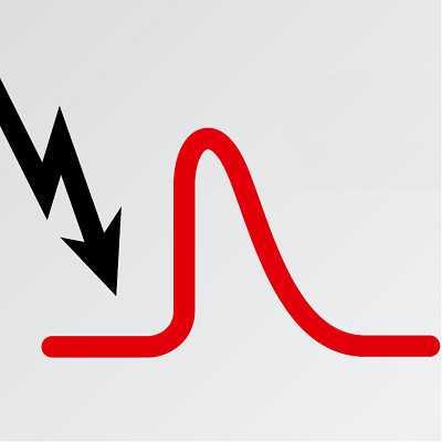
Ringwave
Applicable Test Standard International Electrotechnical Committee (IEC) IEC/EN 61000-4-12: Electromagnetic compatibility (EMC) - Testing and Measurement Techniques - Ringwave Immunity Test Transients on power networks are modified by the cable properties so that in a well-protected domestic or commercial environment, the impulse energy has an oscillatory form. This is known as a “Ring wave”. IEC 61000-4-12 and ANSI C62.41 define the oscillation to have 100kHz. Ring waves are single bipolar oscillatory events. Both the voltage and current waveshapes are similar. Peak current is limited by the equipment location. Ringwave generators have a virtual impedance of 12 or 30 ohms for power network applications.
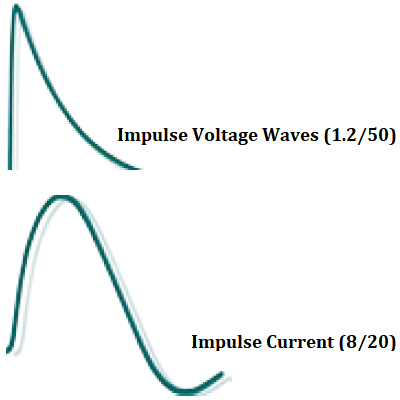
Surge
Applicable Test Standards International Electrotechnical Committee (IEC) IEC 61000-4-5: Electromagnetic compatibility (EMC) - Testing and measurement techniques - Surge immunity test IEC 61000-4-12: Electromagnetic compatibility (EMC) - Testing and measurement techniques - Ring wave immunity test International Telecommunications Union (ITU) K.44: Resistibility tests for telecommunications equipment exposed to overvoltages and overcurrents - Basic recommendation K.20: Resistibility of telecommunication equipment installed in a telecommunications center to overvoltages and overcurrents K.21: Resistibility of telecommunication equipment installed in customer premises to overvoltages and overcurrents American National Standards Institute (ANSI) ANSI C62.41: IEEE Recommended Practice on Surge Voltages in Low Voltage AC Power Circuits Brief Overview The most frequent cause of damage in industrial electronic systems is overvoltage, caused either by switching actions in the equipment itself or by atmospheric discharges such as lightning. If the interference source is in the same circuit as the electronic equipment, the transfer impedance is low, and the impulse takes a current form. If the interference is from some external source, the transfer impedance will be higher resulting in a voltage impulse. To simulate both these conditions, a Combination Wave Generator (CWG) is designed to deliver a voltage impulse into an open circuit and a current impulse into a short circuit. Combination Wave Generators have a virtual impedance (open circuit voltage / short circuit current) of 2 ohms. Power network transients can be modified by the cable properties so that in a well-protected domestic or commercial environment, the impulse energy has an oscillatory form. This is known as a “Ring wave”.
Telecom
Telecommunications equipment, by nature of its application in the telecommunications network, may be exposed to one or more sources of electromagnetic energy. The test equipment in this category is intended to help avoid equipment damage and malfunction because of lightning, 50/60-Hz commercial power fault conditions, Electrostatic Discharge (ESD), Electrical Fast Transient (EFT), Electromagnetic Interference (EMI), operation in the presence of a dc potential difference, and operation in a steady-state induced voltage environment.


)
)
)
)
)
)
)
)
)
)
)
)
)
)
)
)
)
)
)
)