


MIL-STD 461
DEPARTMENT OF DEFENSE INTERFACE STANDARD REQUIREMENTS FOR THE CONTROL OF ELECTROMAGNETIC INTERFERENCE CHARACTERISTICS OF SUBSYSTEMS AND EQUIPMENT This standard establishes interface and associated verification requirements for the control of the electromagnetic interference (EMI) emission and susceptibility characteristics of electronic, electrical, and electromechanical equipment and subsystems designed or procured for use by activities and agencies of the Department of Defense (DoD). Such equipment and subsystems may be used independently or as an integral part of other subsystems or systems. This standard is best suited for items that have the following features: electronic enclosures that are no larger than an equipment rack, electrical interconnections that are discrete wiring harnesses between enclosures, and electrical power input derived from prime power sources. This standard should not be directly applied to items such as modules located inside electronic enclosures or entire platforms. The principles in this standard may be useful as a basis for developing suitable requirements for those applications. Data item requirements are also included. Emission and Susceptibility Designations The emissions and susceptibility and associated test procedure requirements in this standard are designated in accordance with an alphanumeric coding system. Each requirement is identified by a two letter combination followed by a three digit number. The number is for reference purposes only. The meaning of the individual letters is as follows:
- C = Conducted
- R= Radiated
- E = Emission
- S = Susceptibility
- Conducted emissions requirements are designated by “CE--.â€
- Radiated emissions requirements are designated by “RE--.â€
- Conducted susceptibility requirements are designated by “CS--.â€
- Radiated susceptibility requirements are designated by “RS--.â€
- “—“= numerical order of requirement from 101 to 199.
MIL-STD 461 CE101
DEPARTMENT OF DEFENSE INTERFACE STANDARD MIL-STD 461 CE101 - Conducted Emissions, Audio Frequency Currents, Power Leads This test procedure is used to verify that electromagnetic emissions from the EUT do not exceed the specified requirements for power input leads including returns. Applicability This requirement is applicable from 30 Hz to 10 kHz for power leads, including returns, that obtain power from other sources not part of the EUT for surface ships, submarines, Army aircraft & (including flight line) and Navy aircraft *
- * For equipment intended to be installed on Navy aircraft, this requirement is applicable only if the platform contains Anti-Submarine Warfare (ASW) equipment, which operate between 30 Hz and 10 kHz, such as Acoustic (Sonobouy) Receivers or Magnetic Anomaly Detectors (MAD).
- * For AC applications, this requirement is applicable starting at the second harmonic of the EUT power frequency.
- Measurement receivers
- Current probes
- Signal generator
- Data recording device
- Oscilloscope
- Resistor (R)
- LISNs
MIL-STD 461 CE102
DEPARTMENT OF DEFENSE INTERFACE STANDARD MIL-STD 461 CE102 Conducted Emissions, Radio Frequency Potential, Power Leads This test procedure is used to verify that electromagnetic emissions from the EUT do not exceed the specified requirements for power input leads, including returns. Applicability This requirement is applicable from 10 kHz to 10 MHz for all power leads, including returns, which obtain power from other sources not part of the EUT. Limits Conducted emissions on power leads shall not exceed the applicable values shown on Figure CE102-1. Test Equipment
- Measurement receiver
- Data recording device
- Signal generator
- Attenuator, 20 dB, 50 ohm
- Oscilloscope
- LISNs
MIL-STD 461 CE106
DEPARTMENT OF DEFENSE INTERFACE STANDARD MIL-STD 461 CE106 Conducted Emissions, Antenna Port This test procedure is used to verify that conducted emissions appearing at the antenna port of the EUT do not exceed specified requirements. Applicability This requirement is applicable from 10 kHz to 40 GHz for the antenna ports of transmitters, receivers, and amplifiers. The requirement is not applicable to equipment designed with antennas permanently mounted to the EUT. The transmit mode portion of this requirement is not applicable within the bandwidth of the EUT transmitted signal or within ±5 percent of the fundamental frequency, whichever is larger. For Navy shipboard applications with peak transmitter power greater than 1 kW, the 5% frequency exclusion will be increased by an additional 0.1% of the fundamental frequency for each dB above 1 kW of peak power. Frequency Exclusion = ± f * (0.05 + (0.001/dB) * (PtPk [dBm] - 60 [dBm])) Depending on the operating frequency range of the EUT, the start frequency of the test is as follows:
| EUT Operating Frequency Range | Start Frequency of Test |
| 10 kHz to 3 MHz | 10 kHz |
| 3 MHz to 300 MHz | 100 kHz |
| 300 MHz to 3 GHz | 1 MHz |
| 300 MHz to 3 GHz | 10 MHz |
- Receivers: 34 dBμV
- Transmitters and amplifiers (standby mode): 34 dBμV
- Transmitters and amplifiers (transmit mode): Harmonics, except the second and third, and all other spurious emissions shall be at least 80 dB down from the level at the fundamental. The second and third harmonics shall be suppressed to a level of -20 dBm or 80 dB below the fundamental, whichever requires less suppression. For Navy shipboard applications, the second and third harmonics will be suppressed to a level of -20 dBm and all other harmonics and spurious emissions shall be suppressed to -40 dBm, except if the duty cycle of the emissions are less than 0.2%, then the limit may be relaxed to 0 dBm.
- Measurement receiver
- Attenuators, 50 ohm
- Rejection networks
- Directional couplers
- Dummy loads, 50 ohm
- Signal generators. For amplifier testing, a signal generator is required to drive the amplifier that provides the modulation used in the intended application and that has spurious and harmonic outputs that are at least 6 dB below the applicable limit.
- Data recording device
MIL-STD 461 CS101
DEPARTMENT OF DEFENSE INTERFACE STANDARD MIL-STD 461 CS101 - Conducted Susceptibility, Power Leads This test procedure is used to verify the ability of the EUT to withstand signals coupled onto input power leads. There are two methods provided for making measurements of the applied signal. The first uses an oscilloscope with a power input isolation transformer. The second uses a measurement receiver together with a transducer. The transducer electrically isolates the receiver from the EUT power and reduces the levels to protect the receiver. Applicability This requirement is applicable from 30 Hz to 150 kHz for equipment and subsystem AC, limited to current draws ≤ 30 amperes per phase, and DC input power leads, not including returns. This is also applicable to systems that draw more than 30 amps if the system has an operating frequency 150 kHz or less and an operating sensitivity of 1 μV or better (such as 0.5 μV). If the EUT is DC operated, this requirement is applicable over the frequency range of 30 Hz to 150 kHz. If the EUT is AC operated, this requirement is applicable starting from the second harmonic of the EUT power frequency and extending to 150 kHz. Limit The EUT shall not exhibit any malfunction, degradation of performance, or deviation from specified indications, beyond the tolerances indicated in the individual equipment or subsystem specification, when subjected to a test signal with voltage levels as specified on Figure CS101-1. The requirement is also met when the power source is adjusted to dissipate the power level shown on Figure CS101-2 in a 0.5 ohm load and the EUT is not susceptible. Test Equipment
- Signal generator
- Power amplifier
- Oscilloscope or measurement receiver
- Coupling transformer
- Capacitor, 10 μF
- Isolation transformer for oscilloscope use or transducer for measurement receiver use
- Resistor, 0.5 ohm
- LISNs
MIL-STD 461 CS103
DEPARTMENT OF DEFENSE INTERFACE STANDARD MIL-STD 461 CS103 Conducted Susceptibility, Antenna Port, Intermodulation This test procedure is used to determine the presence of intermodulation products that may be caused by undesired signals at the EUT antenna input ports. Applicability This receiver front-end susceptibility requirement is applicable from 15 kHz to 10 GHz for equipment and subsystems, such as communications receivers, RF amplifiers, transceivers, radar receivers, acoustic receivers, and electronic warfare receivers as specified in the individual procurement specification. Limit The EUT shall not exhibit any intermodulation products beyond specified tolerances when subjected to the limit requirement provided in the individual procurement specification. Test Requirements The required test equipment, setup, procedures, and data presentation shall be determined on a case-by-case basis in accordance with the guidance provided in A.5.8 of the appendix of this standard. Preview Standard
MIL-STD 461 CS104
DEPARTMENT OF DEFENSE INTERFACE STANDARD MIL-STD 461 CS104 Conducted Susceptibility, Antenna Port, Rejection of Undesired Signals This test procedure is used to determine the presence of spurious responses that may be caused by undesired signals at the EUT antenna input ports. Applicability This receiver front-end susceptibility requirement is applicable from 30 Hz to 20 GHz for equipment and subsystems, such as communications receivers, RF amplifiers, transceivers, radar receivers, acoustic receivers, and electronic warfare receivers as specified in the individual procurement specification. For Navy ships and submarines, this requirement is applicable for all receivers. The applicable frequencies are a function of the front-end design of the unit being evaluated. Limit The EUT shall not exhibit any undesired response beyond specified tolerances when subjected to the limit requirement provided in the individual procurement specification. Test requirements The required test equipment, setup, procedures, and data presentation shall be determined on a case-by-case basis in accordance with the guidance provided in A.5.9 of the appendix of this standard. Preview Standard
MIL-STD 461 CS105
DEPARTMENT OF DEFENSE INTERFACE STANDARD MIL-STD 461 CS105 Conducted Susceptibility, Antenna Port, Cross-Modulation This test procedure is used to determine the presence of cross-modulation products that may be caused by undesired signals at the EUT antenna ports. Applicability This receiver front-end susceptibility requirement is applicable from 30 Hz to 20 GHz only for receivers that normally process amplitude-modulated RF signals, as specified in the individual procurement specification. Limit The EUT shall not exhibit any undesired response, due to cross modulation, beyond specified tolerances when subjected to the limit requirement provided in the individual procurement specification. Test requirements The required test equipment, setup, procedures, and data presentation shall be determined in accordance with the guidance provided in A.5.10 of the appendix of this standard. Preview Standard
MIL-STD 461 CS109
DEPARTMENT OF DEFENSE INTERFACE STANDARD MIL-STD 461 CS109 Conducted Susceptibility, Structure Current This test procedure is used to verify the ability of the EUT to withstand structure currents. Applicability This requirement is applicable from 60 Hz to 100 kHz for equipment and subsystems that have an operating frequency of 100 kHz or less and an operating sensitivity of 1 μV or better (such as 0.5 μV). Handheld equipment is exempt from this requirement. Limit The EUT shall not exhibit any malfunction, degradation of performance, or deviation from specified indications, beyond the tolerances indicated in the individual equipment or subsystem specification, when subjected to the values shown on Figure CS109-1. Test Equipment
- Signal generator
- Amplifier (if required)
- Isolation transformers
- Current probe
- Measurement receiver
- Resistor, 0.5 ohm
- Coupling transformer
MIL-STD 461 CS114
DEPARTMENT OF DEFENSE INTERFACE STANDARD MIL-STD 461 CS114 Conducted Susceptibility, Bulk Cable Injection This test procedure is used to verify the ability of the EUT to withstand RF signals coupled onto EUT associated cabling. Applicability This requirement is applicable from 10 kHz to 200 MHz for all interconnecting cables, including power cables. For EUTs intended to be installed on ships or submarines, an additional common mode limit of 77 dBμA is applicable from 4 kHz to 1 MHz on complete power cables (highs and returns - common mode test). Limit The EUT shall not exhibit any malfunction, degradation of performance, or deviation from specified indications beyond the tolerances indicated in the individual equipment or subsystem specification, when subjected to an injection probe drive level which has been pre-calibrated to the appropriate current limit shown on Figure CS114-1 and is modulated as specified below. The appropriate limit curve on Figure CS114-1 shall be selected from Table VI. Requirements are also met if the EUT is not susceptible at forward power levels sensed by the directional coupler that are below those determined during calibration provided that the actual current induced in the cable under test is Curve 5 = 115 dBμA, Curve 4 = 103 dBμA, Curve 3 = 95 dBμA, Curve 2 = 89 dBμA and Curve 1 = 83 dBμA across the frequency range. Test Equipment
- Measurement receivers
- Current injection probes (maximum and recommended minimum insertion loss shown on Figure CS114-2)
- Current probes
- Calibration fixture: coaxial transmission line with 50 ohm characteristic impedance, coaxial connections on both ends, and space for an injection probe around the center conductor.
- Directional couplers
- Signal generators
- Plotter
- Attenuators, 50 ohm
- Coaxial loads, 50 ohm
- Power amplifiers
- LISNs
MIL-STD 461 CS115
DEPARTMENT OF DEFENSE INTERFACE STANDARD MIL-STD 461 CS115 Conducted Susceptibility, Bulk Cable Injection, Impulse Excitation This test procedure is used to verify the ability of the EUT to withstand impulse signals coupled onto EUT associated cabling. Applicability This requirement is applicable to all aircraft, space, and ground system interconnecting cables, including power cables. The requirement is also applicable for surface ship and submarine subsystems and equipment when specified by the procuring activity. Limit The EUT shall not exhibit any malfunction, degradation of performance, or deviation from specified indications, beyond the tolerances indicated in the individual equipment or subsystems specification, when subjected to a pre-calibrated signal having rise and fall times, pulse width, and amplitude as specified on Figure CS115-1 at a 30 Hz rate for one minute. Test equipment.
- Pulse generator, 50 ohm, charged line (coaxial)
- Current injection probe
- Drive cable, 50 ohm, 2 meters, 0.5 dB or less insertion loss at 500 MHz
- Current probe
- Calibration fixture: coaxial transmission line with 50 ohm characteristic impedance, coaxial connections on both ends, and space for an injection probe around the center conductor.
- Oscilloscope, 50 ohm input impedance
- Attenuators, 50 ohm
- Coaxial loads, 50 ohm
- LISNs
MIL-STD 461 CS116
DEPARTMENT OF DEFENSE INTERFACE STANDARD MIL-STD 461 CS116 Conducted Susceptibility, Damped Sinusoidal Transients, Cables and Power Leads This test procedure is used to verify the ability of the EUT to withstand damped sinusoidal transients coupled onto EUT associated cables and power leads. Applicability This requirement is applicable from 10 kHz to 100 MHz for all interconnecting cables, including power cables, and individual high side power leads. Power returns and neutrals need not be tested individually. For submarine applications, this requirement is applicable only to cables and leads external to or that exit the pressure hull. Limit The EUT shall not exhibit any malfunction, degradation of performance, or deviation from specified indications, beyond the tolerances indicated in the individual equipment or subsystem specification, when subjected to a signal having the waveform shown on Figure CS116-1 and having a maximum current as specified on Figure CS116-2. The limit is applicable across the entire specified frequency range. Compliance shall be demonstrated at the following frequencies: 0.01, 0.1, 1, 10, 30, and 100 MHz. If there are other frequencies known to be critical to the equipment installation, such as platform resonances, compliance shall also be demonstrated at those frequencies. The test signal repetition rate shall be no greater than one pulse per second and no less than one pulse every two seconds. The pulses shall be applied for a period of five minutes. Test Equipment
- Damped sinusoid transient generator, ≤ 100 ohm output impedance
- Current injection probe
- Oscilloscope, 50 ohm input impedance
- Calibration fixture: Coaxial transmission line with 50 ohm characteristic impedance, coaxial connections on both ends, and space for an injection probe around the center conductor
- Current probes
- Waveform recording device
- Attenuators, 50 ohm
- Measurement receivers
- Coaxial loads, 50 ohm
- LISNs
MIL-STD 461 CS117
DEPARTMENT OF DEFENSE INTERFACE STANDARD MIL-STD 461 CS117 Conducted Susceptibility, Lightning Induced Transients, Cables and Power Leads This test procedure is used to verify the ability of the EUT to withstand lightning transients coupled onto EUT associated cables and power leads. Applicability This requirement is applicable to all safety-critical equipment interconnecting cables, including complete power cables, and individual high side power leads. It is also applicable to non-safety critical equipment with interconnecting cables/electrical interfaces that are part of or connected to equipment performing safety critical functions. It may be applicable to equipment performing non-safety critical functions when specified by the procuring activity. This requirement also has limited applicability to surface ship equipment which have cables routed above deck. Limit The EUT shall not exhibit any malfunction, degradation of performance, or deviation from specified indications, beyond the tolerances indicated in the individual equipment or subsystem specification, when subjected to the levels and lightning transients specified in Table VII and supplemented by the waveform and timing definitions shown on Figures CS117-1 through CS117-8. The applicable transients of Table VII are considered default values and waveforms based upon previous experience and shall be used for the defined equipment functionality when the host platform lightning transient data does not exist. In the event that there is platform lightning transient data available, this data may be used to tailor the requirements with different selected levels or waveforms, pending approval by the procuring activity. Note that the power lines are tested separately as well as within the bundle as defined in the test procedures section and are tested at the levels defined in Table VII. Test Equipment
- Lightning transient generator
- Injection Transformers
- Oscilloscope
- Current monitor probes
- Attenuators, 50 ohm, as needed on current monitor probes
- Voltage monitor probes, high impedance
- Monitor loop, low impedance wire loop
- Calibration loop, low impedance wire loop
- Capacitors, ≥ 28,000 μF for DC power inputs and 10 μF for AC power inputs
- LISNs
MIL-STD 461 CS118
DEPARTMENT OF DEFENSE INTERFACE STANDARD MIL-STD 461 CS118 Conducted Susceptibility, Personnel Electrostatic Discharge (ESD) This test procedure is used to verify the ability of the EUT to withstand personnel borne electrostatic discharge (ESD) in a powered up configuration. Note: This revision added CS117, conducted susceptibility, lightning induced transients, cables and power leads and CS118, personnel borne electrostatic discharge. Applicability and limits The requirement is applicable to electrical, electronic, and electromechanical subsystems and equipment which does not interface with or control ordnance items. This is a new requirement in MIL-STD 461G to address effects of electrostatic discharging on electrical and electronic equipment caused by human ESD. This test methodology is not part of any other military standard. Implementation of this requirement at the subsystem level supports the requirements outlined in MIL-STD-464 for electrostatic charge control at the system level. The EUT shall not exhibit any malfunction, degradation of performance, or deviation from specified indications, beyond the tolerances indicated in the individual equipment or subsystem specification, when subjected to the values shown in Table VIII while discharging from a 150 picofarads capacitor through a 330 ohm resistor with a circuit inductance not to exceed 5 microhenry. Contact discharge at 8kV is required for conductive surfaces. Air discharge is only required where contact discharge cannot be applied. Test Procedure The test procedure presents a controlled method to evaluate the susceptibility of electrical and electronic subsystems to ESD. The intent is to cover subsystem aspects accessible by personnel during EUT operations. The test equipment and procedures are based upon internationally recognized standards such as IEC 61000-4-2. Test Equipment
- ESD Generator, adjustable from ±2kV to ±15kV (minimum range), see Figure CS118-1 and Table X for simplified ESD generator characteristics
- ESD network, 150 picofarads (pF) capacitance, 330 ohm discharge resistance
- Contact discharge tip Figure CS118-2
- Air discharge tip Figure CS118-2
- Electrostatic voltmeter
- Oscilloscope, single event bandwidth ≥ 1 GHz
- ESD current target, input resistance 2 ±5% ohms, Figure CS118-3.
- Attenuator, 20 dB
- Coaxial cable, 50 ohm impedance, ≤ 1 meter
- Metallic ground plane.
- Ionizer or one (1) megohm resistor (1MΩ±10%)
MIL-STD 461 RE101
DEPARTMENT OF DEFENSE INTERFACE STANDARD MIL-STD 461 RE101 Radiated Emissions, Magnetic Field This test procedure is used to verify that the magnetic field emissions from the EUT and its associated electrical interfaces do not exceed specified requirements. Applicability This requirement is applicable from 30 Hz to 100 kHz for radiated emissions from equipment and subsystem enclosures, including electrical cable interfaces. The requirement does not apply to radiation from antennas. For Navy aircraft, this requirement is applicable only for aircraft with ASW equipment which operates between 30 Hz and 10 kHz such as: Acoustic (Sonobouy) Receivers or Magnetic Anomaly Detectors (MAD). Limit Magnetic field emissions shall not be radiated in excess of the levels shown on Figures RE101-1 and RE101-2 at a distance of 7 cm. Test Equipment
- Measurement receivers
- Data recording device
- Loop sensor
- LISNs
- Ohmmeter
- Signal generator
MIL-STD 461 RE102
DEPARTMENT OF DEFENSE INTERFACE STANDARD MIL-STDG 461 RE102 Radiated Emissions, Electric Field This test procedure is used to verify that electric field emissions from the EUT and its associated cabling do not exceed specified requirements. Applicability This requirement is applicable for radiated emissions from equipment and subsystem enclosures, and all interconnecting cables. For equipment with permanently mounted antennas this requirement does not apply at the transmitter fundamental frequency and the necessary occupied bandwidth of the signal. The requirement is applicable as follows:
- Ground - 2 MHz to 18 GHz
- Ships, Surface 10 kHz to 18 GHz
- Submarines 10 kHz to 18 GHz
- Aircraft (Army and Navy) - 2 MHz to 18 GHz
- Aircraft (Air Force) - 2 MHz to 18 GHz
- Space - 10 kHz to 18 GHz
- Measurement receivers
- Data recording device
- Antennas:
- 10 kHz to 30 MHz, 104 cm rod with impedance matching network. The signal output connector shall be bonded to the antenna matching network case
- When the impedance matching network includes a preamplifier (active rod), observe the overload precautions in 4.3.7.3
- Use a square counterpoise measuring at least 60 cm on a side
- 30 MHz to 200 MHz, Biconical, 137 cm tip to tip
- 200 MHz to 1 GHz, Double ridge horn, 69.0 by 94.5 cm opening
- 1 GHz to 18 GHz, Double ridge horn, 24.2 by 13.6 cm opening
- 10 kHz to 30 MHz, 104 cm rod with impedance matching network. The signal output connector shall be bonded to the antenna matching network case
- Signal generators
- Stub radiator
- Capacitor, 10 pF
- LISNs
MIL-STD 461 RE103
DEPARTMENT OF DEFENSE INTERFACE STANDARD MIL-STD 461 RE103 Radiated Emissions, Antenna Spurious and Harmonic Outputs This test procedure is used to verify that radiated spurious and harmonic emissions from transmitters do not exceed the specified requirements. Applicability This requirement may be used as an alternative for CE106 when testing transmitters with their intended antennas. This requirement is met if the emissions do not exceed the applicable RE102 limit in transmit mode. CE106 is the preferred requirement unless the equipment or subsystem design characteristics preclude its use. RE103 should be the preferred method for systems using active antenna or when the antenna impedance has a non-standard impedance curve. The requirement is applicable from 10 kHz to 40 GHz and not applicable within the bandwidth of the EUT transmitted signal or within ±5 percent of the fundamental frequency, whichever is larger. For Navy shipboard applications with peak transmitter power (PtPk) greater than 1 kW, the 5% frequency exclusion is increased by an additional 0.1% of the fundamental frequency for each dB above 1 kW of peak power. Frequency Exclusion = ±f * (0.05 + (0.001/dB) * (PtPk [dBm] - 60 [dBm])) Depending on the operating frequency range of the EUT, the start frequency of the test is as follows:
| Operating Frequency Range (EUT) | Start Frequency of Test |
| 10 kHz to 3 MHz | 10 kHz |
| 3 MHz to 300 MHz | 3 MHz |
| 300 MHz to 3 GHz | 1 MHz |
| 3 GHz to 40 GHz | 10 MHz |
- Measurement receiver
- Attenuators, 50 ohm
- Antennas
- Rejection networks
- Signal generators
- Power monitor
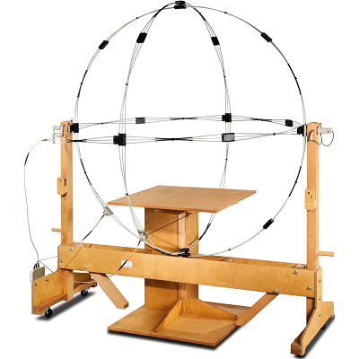
MIL-STD 461 RS101
DEPARTMENT OF DEFENSE INTERFACE STANDARD          MIL-STD 461 RS101 Radiated Susceptibility, Magnetic Field This test procedure is used to verify the ability of the EUT to withstand radiated magnetic fields. Applicability This requirement is applicable from 30 Hz to 100 kHz for equipment and subsystem enclosures, including electrical cable interfaces. The requirement is not applicable for electromagnetic coupling via antennas. For Army and Navy ground equipment, the requirement is applicable only to vehicles having a minesweeping or mine detection capability. For Navy ships and submarines, this requirement is applicable only to equipment and subsystems that have an operating frequency of 100 kHz or less and an operating sensitivity of 1 μV or better (such as 0.5 μV). For Navy aircraft, this requirement is applicable only to equipment installed on ASW capable aircraft, and external equipment on aircraft that are capable of being launched by electromagnetic launch systems. Limit The EUT shall not exhibit any malfunction, degradation of performance, or deviation from specified indications, beyond the tolerances indicated in the individual equipment or subsystem specification, when subjected to the magnetic fields shown on Figures RS101-1 and RS101-2. Test Equipment
- Signal source
- Radiating loop having the following specifications:
- Diameter: 12 cm
- Number of turns: 20
- Wire: No. 12 insulated copper
- Magnetic flux density: 9.5x10⁷ pT/ampere of applied current at a distance of 5 cm from the plane of the loop
- Loop sensor having the following specifications:
- Diameter: 4 cm
- Number of turns: 51
- Wire: 7-41 Litz wire (7 Strand, No. 41 AWG)
- Shielding: Electrostatic
- Correction Factor: See manufacturer’s data for factors to convert measurement receiver readings to decibels above one picotesla (dBpT)
- Measurement receiver or narrowband voltmeter
- Current probe
- LISNs
MIL-STD 461 RS103
DEPARTMENT OF DEFENSE INTERFACE STANDARDÂ Â Â Â Â Â Â Â Â Â MIL-STD 461 RS103 Radiated Susceptibility, Electric Field This test procedure is used to verify the ability of the EUT and associated cabling to withstand electric fields. Applicability This requirement is applicable for equipment and subsystem enclosures and all interconnecting cables. The requirement is applicable as follows:
- 2 MHz to 30 MHz - Army, Navy and optional* for all others
- 30 MHz to 18 GHz - All
- 18 GHz to 40 GHz - Optional* for all
- Signal generators
- Power amplifiers
- Transmit antennas
- Electric field sensors (physically small - electrically short)
- Measurement receiver
- Power meter
- Directional coupler
- Attenuator
- Data recording device
- LISNs
MIL-STD 461 RS105
DEPARTMENT OF DEFENSE INTERFACE STANDARDÂ Â Â Â Â Â Â Â Â Â MIL-STD 461 RS105 Radiated Susceptibility, Transient Electromagnetic Field This test procedure is used to verify the ability of the EUT enclosure to withstand a transient electromagnetic field. Applicability This requirement is applicable to equipment and subsystem enclosures which are exposed to the external electromagnetic environment. For surface ships, this includes external, above deck and exposed below deck installations. The requirement is applicable to Army aircraft for safety critical equipment and subsystems located in an external installation. Limit The EUT shall not exhibit any malfunction, degradation of performance, or deviation from specified indications, beyond the tolerances indicated in the individual equipment or subsystem specification, when subjected to a test signal having the waveform and amplitude shown on Figure RS105-1. At least five pulses shall be applied at the rate of not more than one pulse per minute. Test Equipment
- Transverse electromagnetic (TEM) cell, parallel plate transmission line or equivalent
- Transient pulse generator, monopulse output, plus and minus polarity
- Storage oscilloscope, 700 MHz, single-shot bandwidth (minimum), variable sampling rate up to 1 gigasample per second (GSa/s)
- Terminal protection devices
- High-voltage probe, 1 GHz bandwidth (minimum)
- B-dot sensor probe
- D-dot sensor probe
- LISNs
- Integrator, time constant ten times the overall pulse width
MIL-STD-704
DEPARTMENT OF DEFENSE INTERFACE STANDARD MIL-STD 704 Rev. F Aircraft Electric Power Characteristics This standard establishes the requirements and characteristics of aircraft electric power provided at the input terminals of electric utilization equipment. MIL-HDBK-704-1 through-8 defines test methods and procedures for determining airborne utilization equipment compliance with the electric power characteristics requirements defined herein. Electromagnetic interference and voltage spikes are not covered by this standard. Test requirements Equipment testing is required to demonstrate utilization equipment compatibility with the electric power characteristics of this standard. Utilization equipment test requirements shall be in accordance with the equipment detail specification. The applicable test methods of MIL-HDBK-704 shall be used to determine that the utilization equipment complies with this standard. Aircraft shall be tested to demonstrate that the aircraft electric system power characteristics are within the limits of this standard throughout all operating conditions of the aircraft and its utilization equipment. Aircraft test requirements shall be in accordance with the aircraft detail specification. Preview Standard

RTCA DO-160
RTCA DO-160 Environmental Conditions and Test Procedures for Airborne Equipment DO-160, Environmental Conditions and Test Procedures for Airborne Equipment, published by RTCA (Radio Technical Commission for Aeronautics), is the international standard that defines environmental test conditions and applicable test procedures and criteria for avionic equipment to determine their performance characteristics. All the manufacturers of aeronautic products must meet the requirements of this standard to ensure that their equipment will operate correctly when airborne. The DO-160 document was first published on February 1975, since then the standard has undergone subsequent revisions up through the current Revision G (published in December 2010). More about RTCA DO-160
RTCA DO-160 Section 16
RTCA DO-160 Section 16: Power Input - Environmental Conditions and Test Procedures for Airborne Equipment The purpose of this standard is to define test conditions and procedures for AC and DC electrical power applied to the terminals of the equipment under test. It covers the following electrical power supplies:
- 14 V dc, 28 V dc and 270 V dc
- 115 Vrms ac and 230 Vrms ac at either a nominal 400 Hz frequency or over a variable frequency range which includes 400 Hz.
RTCA DO-160 Section 17
RTCA DO-160 Section 17: Voltage Spike The purpose of this standard is to determine whether the EUT can operate as required during and/ or after voltage spikes are applied to the AC and/or DC power input(s). Any method of generating the spike may be used, provided that the pulse produced has a duration of at least 10 microseconds, a rise-time of less than 2 microseconds, and a source impedance of 50 ohms. A minimum of 50 voltage spikes are applied within 1 minute. This test is very similar to MIL-STD-461F test method CS106 [3]. The main adverse effects to be anticipated are:
- Permanent damage, component failure, insulation breakdown.
- Susceptibility degradation or changes in equipment performance.
- Category A: Equipment intended primarily for installation where a high degree of protection against damage by voltage spikes is required is identified as Category A. The Category A Test Level is 600 volts.
- Category B: Equipment intended primarily for installations where a lower standard of protection against voltage spikes is acceptable is identified as Category B. The Category B test level is twice the AC (rms) and/or DC line voltage (or 200 volts, whichever is less).
RTCA DO-160 Section 18
RTCA DO-160G Section 18: Audio Frequency Conducted Susceptibility - Power Inputs This test determines whether the equipment will accept frequency components of a magnitude normally expected when the equipment is installed in the aircraft. This test is performed to determine that the EUT will operate as specified when audio frequency interference is applied to the AC and/or DC power input. The test setup and procedure are nearly identical to MIL-STD 461F test method CS101, with the only difference being the actual test level and frequency range. The audio frequency interference is transformer coupled onto each power input lead, and the peak-to-peak voltage level of the interference signal is measured across the power input and return leads. Test levels are up to 8% of the nominal AC input voltage, and the frequency range is as broad as 10 Hz to 150 kHz. Equipment Categories There are three DC power Equipment Categories (R, B, and Z) that indicate the type of power used by the equipment and the type of DC power source with which the equipment is compatible. Two AC power Equipment Categories are specified (R & K). Category R is used with an additional designation (a two character code), placed in parenthesis following the Category designator, indicates that the equipment has been tested for use with Constant Frequency (CF), Narrow Variable Frequency (NF), or Wide Variable Frequency (WF). Category K designates that the EUT has been tested for use with any type of AC power input, and tested to a higher level of voltage distortion than category R. More about RTCA DO-160 Section 18 More about RTCA DO-160G Section 18
RTCA DO-160 Section 20
RTCA DO-160G Section 20: Radiated Frequency Susceptibility (Radiated and Conducted) These tests determine whether equipment will operate within performance specifications when the equipment and its interconnecting wiring are exposed to a level of RF modulated power, either by a radiated RF field or by injection probe induction onto the power lines and interface circuit wiring. Two test procedures are used:
- From 10 kHz to 400 MHz, the equipment under test (EUT) is subjected to RF signals coupled by means of injection probes into its cable bundles
- For frequencies between 100 MHz and the upper frequency limit, the EUT is subjected to radiated RF fields. There is an intentional overlap of the tests from 100 to 400 MHz.
RTCA DO-160 Section 22
RTCA DO-160 Section 22: Lightning Induced Transient Susceptibility These test methods and procedures are provided to verify the capability of equipment to withstand a selection of test transients defined in this section which are intended to represent the induced effects of lightning. The wave-forms and levels, and the pass/fail criteria for equipment performance during the test shall be listed in the applicable equipment specification. Two groups of tests may be used for equipment qualification:
- The first is a damage tolerance test performed using pin injection
- The second group evaluates the functional upset tolerance of equipment when transients are applied to interconnecting cable bundles
- Pin test waveform set letter (A or B) as designated in Table 22-1.1 or Z or X
- Pin test level (1 to 5) as designated in Table 22-2 or Z or X
- Cable bundle single and multiple stroke test waveform set letter (C through K) as designated in Table 22-1.2 or Z or X
- Cable bundle single and multiple stroke test level (1 to 5) as designated in Table 22-3 and Table 22-4 or Z or X
- Cable bundle multiple burst test waveform set letter (L or M) as designated in Table 22-1.2 or Z or X
- Cable bundle multiple burst test level (1 to 5) as designated in Table 22-5 or Z or X
RTCA DO-160 Section 25
RTCA DO-160 Section 25: Electrostatic Discharge The electrostatic discharge test is designed to determine the immunity or the ability of equipment to perform its intended function without permanent degradation of performance as a result of an air discharged electrostatic pulse. The immunity to electrostatic discharge shall be determined by the ability of the equipment under test (EUT) to withstand a series of electrostatic discharge pulses at a test level of 15,000 volts, directed at specific human contact locations on the EUT. The quantity of pulses shall be ten (10) in each of the selected locations and in both positive and negative voltage polarities (10 positive and 10 negative). Equipment Category Category A - Electronic equipment that is installed or operated during normal operation and/or maintenance of the aircraft. This test is applicable for all equipment and surfaces which are accessible during normal operation and/or maintenance of the aircraft. This test is not applicable to connector pins. More about RTCA DO-160 Section 25


)
)
)
)
)
)
)
)
)
)
)
)
)
)
)
)
)
)
)
)