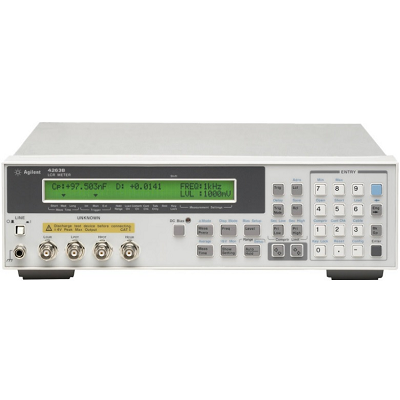
| Measurement Functions |
| Measurement Parameters | |Z|, |Y|, q, R, X, G, B, L, C, Q, D, ESR Opt. 001: Add DCR (dc resistance), N (turns ratio), and M (mutual inductance) measurement. |
| Measurement Circuit Mode | Series and parallel |
| Mathematical Functions | Deviation and percent deviation |
| Test Cable Lengths | 0 m, 1 m, 2 m, 4 m (freq. = 100/120/1k Hz); 0 m, 1 m, 2 m (freq. = 10k/20k Hz); 0 m, 1 m (freq.= 100 kHz) |
| Test Signal Information |
| Test Frequency | 100 Hz, 120 Hz, 1 kHz, 10 kHz, and 100 kHz Opt. 002: Add 20 kHz test frequency |
| Frequency Accuracy | ± 0.01% (freq. = 100 Hz, 1 kHz, 10 kHz, (20 kHz, 100 kHz), ± 1% (freq. = 120 Hz) |
| Output Impedance | 100 Ω ± 10%, 25 Ω ± 10% (± 1 Ω range) |
| AC Test Signal Level | 20 m to 1 Vrms in 5m Vrms steps |
| Accuracy | ± (10% + 10 mV) |
| Internal dc Bias | Level: 1.5 and 2 V Accuracy: ± (5% + 2 mV) |
| External dc Bias | 0 to +2.5 V |
| Measurement Range | Parameter | Measurement Range |
| |Z|, R, X | 1 mΩ to 100 MΩ |
| |Y|, G, B | 10 nS to 1000 S |
| C | 1 pF to 1 F |
| L | 10 nH to 100 kH |
| D | 0.0001 to 9.9999 |
| Q | 0.1 to 9999.9 |
| q | -180° to +180° |
| DCR | 1 mΩ to 100 MΩ |
| N | 0.9 to 200 (unspecified) |
| L, M | 1 µH to 100 H (unspecified) |
| D% | -999.99% to +999.99% |
| Measurement Accuracy | ± 0.1% (basic) (for |Z|, R, X, |Y|, G, B, C, L) |
| Measurement Time | Mode | Time (typical) |
| Short | 25 ms |
| Medium | 65 ms |
| Long | 500 ms |
| Test Signal Level Monitor | Voltage and current |
| Front-End Protection | Internal circuit protection when a charged capacitor is connected to the input terminals. The maximum capacitor voltage is: Vmax = ±/font> (8/C) typical @ Vmax ± 250 V; Vmax = ± (2/C) typical @ Vmax ± 1000 V, C is in Farads. |
| Display Digits | 3, 4, or 5 (selectable) |
| Correction Function |
| Zero OPEN/SHORT | Eliminates measurement errors due to stray parasitic impedances in the test fixtures. |
| Load | Improves measurement accuracy by using a calibrated device as a reference. |
| Comparator Function | HIGH/IN/LOW for each primary measurement parameter and secondary measurement parameter. |
| Contact Check Function | Contact failure between the test fixture and device can be detected. Additional time for contact check: 5 ms. |
| Other Functions |
| Save/Recall | Ten instrument setups can be saved/recalled from the internal nonvolatile memory. |
| Continuous Memory Capability | If the instrument is turned off, or if a power failure occurs, instrument settings (except dc bias on/off) are automatically memorized (± 72 hours at 23° ± 5° C). |
| HP-IB Interface | All control settings, measured values, and comparator information. |
| Handler Interface | All output signals are negative-logic, optically isolated open collectors. Output signals include HIGH/IN/LOW, no contact, index, end of measurement, and alarm. Input signals include keylock and external trigger. |
| GENERAL SPECIFICATIONS |
| Power Requirements | 90 to 132 V or 198 to 264 V, 47 to 66 Hz, 45 VA max. |
| Operating Temperature | 0 to 45°C |
| Size | 320 mm W X 100 mm H X 300 mm D (12.6 in X 3.94 in X 11.81 in) |
| Weight | 4.5 kg (9.9 lb) |
| Key Literature | HP 4263B LCR Meter Product Overview, p/n 5964-6181E LCR Meters, Impedance Analyzers and Test Fixtures Selection Guide, p/n 5952-1430 |
)
)
)
)
)
)
)
)
)
)
)
)
)
)
)
)
)
)
)