| Performance |
| Maximum Continuous DC Current (±50VDC) |
| 4301-60 |
60A |
| 4301-120 |
120A |
| 4301-180 |
180A |
| 4301-240 |
240A |
| Maximum Pulse DC Current (up to ±100VDC) |
| 4301-60 |
200A |
| 4301-120 |
400A |
| 4301-180 |
600A |
| 4301-240 |
800A |
| Voltage Gain |
20 |
| Maximum Input Voltage |
±10V, unbalanced |
| Indicators and Controls (4301 system amplifier modules) |
| LED Displays |
Indicators for Run, Ready, Standby, and Stop status, and Fault conditions in the output stage. |
| LCD Display |
Can be user-configured for up to four simultaneous displays reporting one, two, or all four of the following: Voltage Peak, Voltage RMS, Current Peak and Current RMS. When the amplifier module is in a Fault condition, the LCD Display lists the type of fault condition and gives suggested corrective action. |
| Navigation Buttons |
The Navigation Buttons provide four arrow keys to allow navigation through the various LCD display options. |
| Soft Touch Switches |
Soft touch switches allow the selection of Run (Enable), Stop and Reset functions. |
| Compensation Setting |
A four-position rotary control allows the selection of optimum compensation settings according to the total current required at the system output. |
| Compensation LEDs |
When the amplifier module is receiving AC power, the colored LED associated with the selected Compensation setting will be lit. |
| Inputs and Outputs |
| Signal Input |
A BNC connector located on the cabinet front input/output panel accepts input from an arbitrary waveform generator. |
| External Trigger Output |
A BNC connector located on the cabinet front input/output panel provides the signal to the Trigger In connector on the AWG. |
| Current Monitor Output: |
A BNC connector located on the cabinet front input/output panel provides scaled voltage output for current monitoring: |
| 4301-60 |
20A output = 1V monitor output. |
| 4301-120 |
40A output = 1V monitor output. |
| 4301-180 |
60A output = 1V monitor output. |
| 4301-240 |
80A output = 1V monitor output. |
| 4301-60 |
20A output = 1V monitor output. |
| Voltage Monitor Output |
A BNC connector located on the cabinet front input/output panel provides scaled voltage output for voltage monitoring: 10V output = 1V monitor output. |
| Signal Output |
250A Pin Plug connectors (or optional Anderson SB350 connectors) provide signal output to the equipment under test. |
| Protection |
| Fault |
The Fault LED on an amplifier module will light if the module€™s output stage stops operating. If this happens, contact AE TECHRON for servicing information. |
| AC Under/Over Voltage Protection:
|
If the AC line voltage rises or drops more than10% of the nominal operating voltage, the system will be forced to Standby. |
| Over Current
|
Each amplifier module contains breaker protection on both the unit€™s main power supply and the low-voltage supplies. The 4301 system provides a Main Power breaker switch and an Auxiliary Power breaker switch located inside the cabinet rear door. |
| Over Temperature |
Each amplifier module contains separate output transistor, heat-sink and transformer temperature monitoring and protection circuits. |
| Operating Temperature |
10°C to 50°C (50°F to 122°F), Maximum Output Power de-rated above 30°C (86°F).) |
| Humidity |
70% or less, non-condensing |
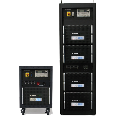
| Dimensions (H x W x D) |
| 4301-240 and 4301-180 |
74 in. x 22 in. x 31.5 in. (188 cm x 55.9 cm x 80 cm). |
| 4301-120 and 4301-60 |
52 in. x 22 in. x 31.5 in. (132 cm x 55.9 cm x 80 cm). |
| Net Weight |
| 4301-240 |
1050 lbs. (476 kgs) |
| 4301-180 |
897 lbs. (316 kgs) |
| 4301-120 |
589 lbs. (267 kgs) |
| 4601-60 |
436 lbs. (198 kgs) |

